
 admin
Electromagnetic Flow Meter Guide: Cooling Tower Makeup Water
Direct Answer
An electromagnetic flow meter for cooling tower makeup water should be installed on the dedicated makeup water supply line — the pipe that feeds fresh water into the cooling tower basin to replace losses from evaporation, blowdown, and drift — and not on the recirculation loop between the tower and the condenser/chiller. If the makeup line splits into multiple branches, bypasses, or is shared with other utility loads, the meter must be placed at a point that captures the full, isolated makeup volume, or multiple meters are required with a defined summation boundary.
Understanding the Three Water Streams
Cooling tower systems involve three distinct flows, and confusing them is the most common measurement-point mistake.
Makeup Water
This is the fresh water entering the system to replace what is lost. It is typically a smaller-diameter line connected to a city main, well, or treated water source, usually controlled by a float valve or solenoid valve at the tower basin.
Recirculation Water
This is the large-volume water continuously circulated between the cooling tower and the heat-rejecting equipment (chillers, condensers, process heat exchangers). Recirculation flow is driven by the main circulation pump and is many times larger than makeup flow.
Blowdown Water
This is the water deliberately discharged from the system to control the concentration of dissolved solids, which otherwise rise as evaporation leaves minerals behind.
Three-Stream Comparison Table
| Stream | Purpose | Typical Line Size | Flow Pattern | Correct Meter Role |
|—|—|—|—|—|
| Makeup Water | Replace evaporation, drift, blowdown losses | Smaller than recirculation line | Intermittent or float-valve controlled | Primary measurement target for consumption tracking |
| Recirculation Water | Transfer heat between tower and condenser/chiller | Largest line in the system | Continuous, high volume | Not equivalent to makeup consumption |
| Blowdown Water | Control dissolved solids concentration | Smallest line, often with a control valve | Intermittent or continuous bleed | Separate measurement point if balance-based water accounting is required |
Why Recirculation Flow Cannot Represent Makeup Consumption
Recirculation flow reflects the volume moved by the circulation pump to reject heat — it has no direct relationship to the amount of fresh water consumed. A tower can recirculate the same (or larger) volume of water continuously while makeup demand varies with ambient conditions, cycles of concentration, and blowdown settings. Reading recirculation flow and assuming it represents makeup usage will produce numbers that do not match water bills, basin level trends, or blowdown control logic. Each stream must be measured at its own physical location.
Multiple Makeup Branches, Bypasses, and Shared Supply Lines
Many cooling tower installations do not have a single clean makeup pipe. Common complications include:
- Multiple makeup branches: Several towers or cells fed from a common header, each with its own float valve.
- Bypass lines: Manual or automatic bypass piping used during maintenance or valve failure, which can route water around the intended metering point.
- Shared supply lines: The makeup line may tap off a larger utility water main that also serves other equipment.
In these cases, the measurement boundary must be clearly defined before selecting an installation point:
- If all branches merge into one header before entering the basin, install the meter downstream of that merge point and upstream of any branch-level bypass.
- If branches remain separate and must be tracked individually, each branch needs its own meter, with totals summed at the platform or controller level.
- If the makeup line shares a main with non-cooling-tower loads, the meter must be placed after the branch point dedicated solely to the cooling tower, not on the shared main.
A piping diagram review before installation is the only reliable way to confirm where the true makeup boundary lies.
Full-Pipe Operation, Conductivity, and Model-Specific Requirements
Electromagnetic flow meters depend on specific physical conditions to produce a valid signal, and these conditions must be verified at the proposed installation point:
- Full-pipe operation: The sensor must always have the pipe completely filled with liquid. Partial-fill conditions — common on gravity-fed basin inlets or lines with air pockets — will distort the measurement regardless of the meter’s rated accuracy.
- Conductivity: The measured liquid must be electrically conductive. Not every makeup water source meets this requirement; deionized water, reverse-osmosis permeate, or very low-mineral-content water may fall below the conductivity threshold needed for reliable signal generation. Source water quality should be confirmed before meter selection, not assumed.
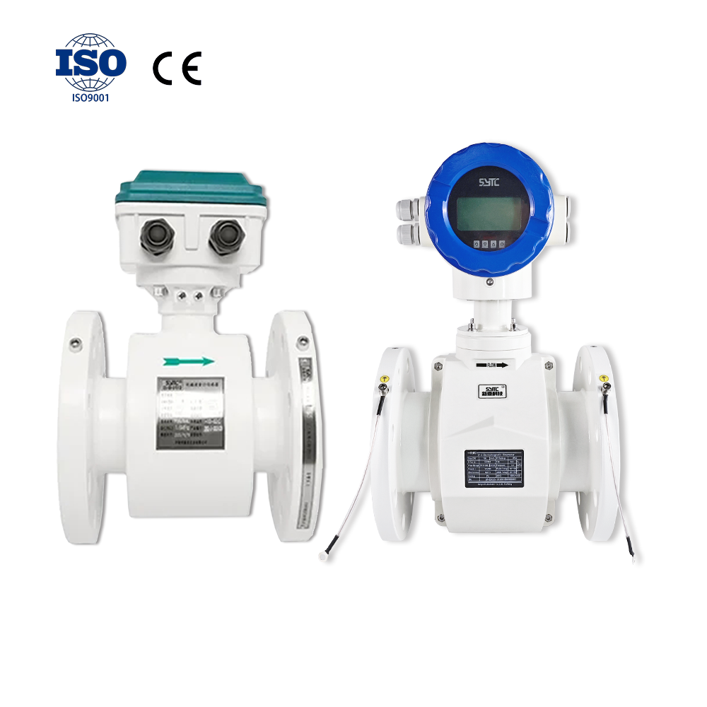
- Model-specific installation requirements: Different product lines in the electromagnetic flowmeter family — including integral or split-type sensors, insertion-style units, and submersible battery-powered units — have different orientation, grounding, and electrode placement requirements. These must be matched to the specific pipe size, material, and installation environment rather than treated as universal.
Piping Verification Checklist
Before finalizing a measurement location, confirm the following:
- [ ] The makeup water line is physically separated from the recirculation loop at the proposed meter location
- [ ] All makeup branches are either merged into a single measurable point or individually metered
- [ ] Bypass piping does not allow flow to bypass the meter during normal operation
- [ ] The pipe section remains full under all expected flow conditions (no vacuum breaks, open vents, or gravity-drop sections at the meter point)
- [ ] Water conductivity at the makeup source has been checked and documented
- [ ] Pipe material, diameter, and whether the pipe can accommodate a full-bore sensor or requires an insertion-type unit have been confirmed
- [ ] Grounding provisions suitable for the pipe material (metallic vs. non-metallic, lined vs. unlined) are planned
- [ ] Upstream/downstream flow conditions and the orientation of the sensor relative to the pipe run have been reviewed with the meter manufacturer for the specific model selected
Frequently Asked Questions
Can I install the flow meter on the condenser water return line instead of the makeup line?
No. The condenser water return line carries recirculation flow, not makeup flow. These are different measurement objectives and will produce different numbers.
Does factory calibration of the meter affect where I should install it?
No. Factory calibration confirms the meter’s internal measurement performance before shipment; it does not determine where the meter should be installed. Measurement-point selection depends on your piping layout, the stream you intend to measure, and site-specific conditions — this must be evaluated independently of calibration status.
What if my makeup water comes from a low-conductivity source?
Conductivity should be checked against the meter’s requirements before installation. Not all makeup water sources meet the conductivity levels needed for electromagnetic flow measurement, and this should not be assumed without verification.
Can one meter measure makeup, recirculation, and blowdown together?
No. These are three physically separate streams with different flow characteristics and purposes. Each requires its own measurement point if individual tracking is needed.
Conclusion
Correct placement of an electromagnetic flow meter for cooling tower makeup water depends on isolating the dedicated makeup line from recirculation and blowdown streams, accounting for any branches or bypasses, and confirming that the pipe section meets full-pipe and conductivity requirements for the selected meter model. These site-specific factors — not the meter’s factory calibration — determine whether the measurement point will produce usable data.
Request a Site-Specific Review
To determine the correct measurement location for your system, share the following with your flow measurement provider:
- Makeup water piping diagram (including branches, bypasses, and shared lines)
- Water source and conductivity data
- Expected flow range
- Pipe size and material
- Operating temperature and pressure
- Signal and communication requirements for your control system
Providing this information allows for a measurement-point recommendation suited to your specific cooling tower configuration, rather than a generic installation guideline.
https://www.sytcflowmeter.com/
Kaifeng Xinya Instrument Co., Ltd.